SMA là viết tắt của subminiature A được phát triển từ những năm 1960. Đầu nối sử dụng cho giao diện luồng, trở kháng 50 Ω cho dải tần lên đến 18 GHz. Đầu nối hiệu suất cao có kích thước nhỏ gọn và độ bền vượt trội.
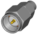
Dùng trong thiết bị radar pha mảng, hệ thống hạ cánh ILS và thiết bị khác, SMA connector cho cáp đồng trục và SMA Plug-to-Jack cung cấp giao diện chính xác và đơn giản cho thiết bị vi sóng. Phù hợp với tiêu chuẩn quân sự MIL-C-39012 và CECC 22110/111.
Tính năng và lợi ích
- Băng thông lên đến 18 GHz với đầu nối bằng thép không gỉ và ¼ - 36 khớp nối ren hiệu suất cao với thiết kế nhỏ gọn.
- Sản phẩm thương mại (Brass SMA) mạ niken hoặc mạ vàng, với 250 chu kỳ tháo lắp.
- Available for .085" and .141" diameter semi-rigid cables and all the standard flexible cables including double shielded RG-316.
- Phase Adjustable SMA connectors provide ease of mechanical screw adjustments, compared to the delays and expense of laborious cable-trimming.
Base Stations |
Cable Assemblies |
Components |
|||
Instrumentation |
Mil/Aero |
PC/LAN |
|||
Process Controls |
Telecom |
Stainless Steel SMA Specifications
Electrical |
|
Impedance |
50 Ω |
Frequency Range |
.141" & .085" semi-rigid cable: 0-18 GHz |
Voltage Rating |
RG-55, 58, 141, 142, 223, 303: 500 volts peak |
Dielectric Withstanding Voltage |
.141" & RG-58 Cables: 1,000 VRMS |
VSWR |
Straight connector, .141": 1.05 + .005 f (GHz) |
Contact Resistance |
Center contact: 2.0 mΩ |
Insulation Resistance |
5,000 MΩ minimum |
Insertion Loss |
dB maximum = .03√[f(GHz)] |
RF Leakage |
-60 dB minimum |
Mechanical |
|
Mating |
.250-36 threaded coupling |
Mating Torque |
Minimum: 2 inch pounds (22 N.cm) |
Coupling Nut Retention |
Axial force: 100 inch pounds min. (300 N.cm) |
Connector Affixment to Cable |
Crimp and solder types |
Cable Affixment to Center Contact |
Solder, except as noted |
Contact Captivation |
All types unless noted otherwise |
Cable Retention (Crimp) |
RG-58, 303 and .141": 60 lbs. minimum |
Connector Durability |
500 mating and unmating cycles @ 12 cycles per minute |
Material |
|
Bodies, Coupling Nuts, Other Metal Parts (except as noted) |
Non-magnetic stainless steel style per QQ-S-764, Type 303 |
Contacts |
Beryllium copper per QQ-C-530, heat treated per MIL-H-7199 |
Center Contact Plating |
.00005" minimum gold per MIL-G-45204, type 1, grade C. Gold over nickel unless otherwise requested. |
Plating (Other Metal Parts) |
Gold plated or passivated to meet the finish and corrosion requirements of MIL-C-39012 |
Insulator |
TFE fluorocarbon per ASTM D1457 |
Gaskets |
Silicone rubber, per MIL-R-5847 and ZZ-R-765 class IIB, grade 65-75. |
Lock washers |
Stainless steel, internal tooth supplied with all bulkhead mounted connectors |
Crimp Ferrule |
Seamless copper tubing alloy #122 (DHP), hard drawn to Rockwell 58-77 on 30-T scale per ASTM B75 |
Environmental |
|
Temperature Range |
- 65°C to +165°C |
Thermal Shock |
MIL-STD-202 method 107 (test condition B) except high temperatures @ + 200°C |
Vibration |
MIL-STD-202 method 204 (test condition D) |
Shock |
MIL-STD-202 method 213 (test condition I). No discontinuity permitted. |
Corrosion |
MIL-STD-202 method 101 (test condition B) 5% salt solution |
Moisture Resistance |
MIL-STD-202 method 106, except step 7b (vibration) omitted, and high humidity measurements do not apply |
Weatherproofing |
Crimp type: heat shrink tubing |
Altitude |
MIL-STD-202 method 105 (test condition C), no corona at 70,000 feet. |
Military Specifications |
|
MIL-C-39012 & MIL-C-83517 SMA Specification Sheets |
As applicable |
Note: These characteristics are typical but may not apply to all connectors.
Brass SMA Specifications
Electrical |
|
Impedance |
50 Ω |
Frequency Range |
.141" & .085" semi-rigid cable: 0-18 GHz |
Voltage Rating |
RG-58, 141, 142: 500 volts peak |
Dielectric Withstanding Voltage |
.141" & RG-58 Cables: 1,000 VRMS |
VSWR |
Straight connector, .141": 1.05 + .005 f (GHz) |
Contact Resistance |
Center contact: 2.0 mΩ |
Insulation Resistance |
5,000 MΩ |
Insertion Loss |
dB maximum = .06v[f(GHz)] |
RF Leakage |
-90 dB minimum @ 2.3 GHz |
Mechanical |
|
Mating |
.250-36 threaded coupling |
Mating Torque |
Minimum: 2 inch pounds (12 N.cm) |
Connector Durability |
100 matings |
Material |
|
Bodies, Coupling Nuts, Other Metal Parts (except as noted) |
Brass per QQ-B-626 |
Contacts |
Male: Brass |
Center Contact Plating |
.000030" minimum gold |
Plating (Other Metal Parts) |
Standard .000010" gold or nickel plated |
Insulator |
TFE fluorocarbon |
Gaskets |
Silicone rubber |
Crimp Ferrule |
Seamless copper tubing alloy |
Environmental |
|
Temperature Range |
- 65°C to +165°C |
Thermal Shock |
MIL-STD-202 method 107 (test condition B) except high temperatures @ + 200°C |
Vibration |
MIL-STD-202 method 204 (test condition D) |
Shock |
MIL-STD-202 method 213 (test condition I). No discontinuity permitted. |
Corrosion |
MIL-STD-202 method 101 (test condition B) 5% salt solution |
Moisture Resistance |
MIL-STD-202 method 106, except step 7b (vibration) omitted, and high humidity measurements do not apply |
Weatherproofing |
Crimp type: heat shrink tubing |
Altitude |
MIL-STD-202 method 105 (test condition C), no corona at 70,000 feet. |
Military Specifications |
|
MIL-C-39012 & MIL-C-83517 SMA Specification Sheets |
As applicable |
Note: These characteristics are typical but may not apply to all connectors.
Phase Adjustable SMA Specifications
Electrical |
|
Impedance |
50 Ω |
Frequency Range |
DC-18 GHz |
Insertion Loss |
dB maximum |
VSWR |
Straight connector, .141: 1.05 + .005 f(GHz) Straight connector, RG-55: 1.15 + .011 f (GHz) Straight connector, RG-122: 1.15 + .02 f (GHz) Straight connector, RG-178: 1.20 + .025 f (GHz) Right Angle connector, .141: 1.10 + .01 f (GHz) Right Angle connector, RG-55: 1.15 + .02 f (GHz) Right Angle connector, RG-122: 1.15 + .03 f (GHz) Right Angle connector, RG-178: 1.20 + .03 f (GHz) |
Phase Angle Adjustment Range in Degrees |
For adapter 901-508 and plug 901-509 = 0° to [10 x f(GHz)]° maximum |
Phase Angle Change per Revolution of Adjustment Nut in Degrees |
For adapter 901-508 and plug 901-509 = [0.636 x f(GHz)]° |
Voltage Rating |
500 VRMS peak |
Mechanical |
|
Mating |
Mating face dimensions compatible with the mating requirements of MIL-C-39012/55 (Type SMA) |
Connector Durability |
500 cycles of mating and unmating without deterioration |
Material |
|
Center Contact |
Beryllium copper, Gold plated |
Connector Body |
Brass or Beryllium Copper, Gold plated |
Adjusting Nuts and Locking Nuts |
Brass with ASTRO plate finish |
Connector Coupling Nut |
Stainless steel, passivated |
Insulation |
TFE |
Environmental |
|
Shock |
MIL-STD-202 method 213 (test condition I) |
Vibration |
MIL-STD-202 method 204 (test condition D) |
Corrosion |
MIL-STD-202 method 101 (test condition B) |
Temperature Range |
- 65°C to +165°C |
Military Specifications |
|
MIL-C-39012 & MIL-C-83517 SMA Specification Sheets |
As applicable |
Note: These characteristics are typical but may not apply to all connectors.
Reverse Polarity SMA Specifications
Electrical |
|
Impedance |
50 Ω |
Frequency Range |
Semi rigid 0 - 18 GHz |
Voltage Rating |
375 volts peak |
Dielectric Withstanding Voltage |
1,000 volts rms |
VSWR |
Straight connectors on .141" S/R: 1.05 + .005 f (GHz) |
Insertion Loss |
.03 v[f (GHz)] dB maximum |
Insulation Resistance |
5,000 MΩ |
RF Leakage |
-60 dB minimum |
Mechanical |
|
Mating |
.250-36 threaded coupling |
Cable Affixment |
Crimp or solder types |
Center Conductor |
Solder |
Cable Retention |
60 - 80 lbs depending on cable |
Material |
|
Center Contact |
Beryllium copper, gold-plated |
Crimp Ferrule |
Copper tubing |
Other Metal Parts |
Non-magnetic passivated stainless steel or brass, gold or silver-plated |
Insulators |
TFE |
Gaskets |
Silicone rubber |
Environmental |
|
Temperature Range |
-65°C to +165°C |
Moisture Resistance |
MIL-STD-202, method 106, test condition B |
Corrosion |
MIL-STD-202, method 101, test condition B |
Vibration |
MIL-STD-202, method 204, test condition B |
Note: These characteristics are typical but may not apply to all connectors.